|
|
|
Freescale
MC9S08QG8/4
|
|
|
Code
Example #10
|
| 2011.12.31 | ||
| 2012.01.01 | - recent update | |
| - added LCD info | ||
| - added Example 4. | ||
| 2012.01.13 | - Introduction to Examples | |
| - added explanations, various comments | ||
| - added example 5 | ||
| 2012.01.15 | - Global and local variables | |
| - Stacks | ||
| 2012.01.16 | - Interrupts | |
| 2012.01.19 | - 7-Segment LED interface | |
| 2012.02.13 | - Example #10 - Four 7-segment LED multiplexed | |
| 2012.02.14 | - Modifications to Example #10 | |
| 2012.03.14 | - Examples on individual pages | |
| Example #1 | Simple ASM program vs C program | |
| Watchdog Memory I/O Model Page Zero Addressing Infinite Loop External Crystal |
||
| Example #2 | Flashing LED |
|
| Software delay | ||
| Example #3 | Character Output | |
| Serial Transmit Data LCD Display Function Prototypes |
||
| Example #4 | Text Message | |
| Characters, Strings and Pointers |
||
| Example #5 | Timer test with oscilloscope |
|
| Example #6 | Timer test with flashing LED | |
| Gobal and Local variables Stacks Subroutines |
||
| Example #7 | Timer test with flashing LED using interrupts | |
| Interrupts | ||
| Example #8 | Single Hexadecimal Display on 7-segment LED | |
| Common Cathode Display | ||
| Example #9 | Single Hexadecimal Display on 7-segment LED | |
| Common Anode Display | ||
| Example #10 | Four multiplexed 7-segment Common Anode LED | |
| Displaying decimal digits Switch/Case statements |
||
| Example #11 | Four multiplexed 7-segment Common Anode LED | |
| Displaying 8-bit and 16-bit integers as hexadecimal digits | ||
Eventually, there comes the necessity and challenge to be able to determine and confirm that your program is generating correct numerical results. This can be accomplished using the DEBUG feature of your IDE (Integrated Development Environment). Sometimes the DEBUG feature cannot be used when the test must be conducted under real time operating conditions.
Multiple LEDs may not be a choice if there are no remaining input/output pins available. The solution calls for a means of displaying text (ASCII characters) transmitted to a suitable text display such as an LCD module or a PC screen. This solution is particularly efficient since it requires a single output pin on the MCU, the SCI TXD signal (Serial Communications Interface - Transmit Data), pin-11 on the MC9S08QG8 chip. This has been demonstrated in Example #4.
We can display 8-bit data in binary as a sequence of zeros and ones. We will leave this as an exercise.
In the next two examples, we will make use of four seven-segment LED digits in order to display numeric information in both decimal and hexadecimal notation.
added - 2012.02.13
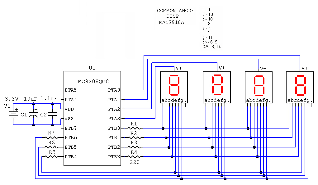
COMMON ANODE DISPLAYS
In this example, we will display the numerals 1 - 2 - 3 - 4 on the four displays.
#include <MC9S08QG8.h>
// 4-digit COMMON ANODE LED Display
// Declare global constants
here
#define COUNT_LIMIT 61
// Declare global variables
byte Count, TimerCount;
byte d3, d2, d1, d0;
byte select;
byte Display[16];
void EnableInterrupts(void)
{
asm
{
CLI
}
}
void Init(void)
{
SOPT1 = 0x52; // disable COP watchdog
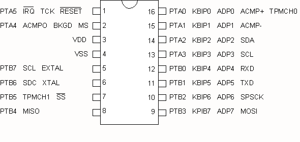
PTADD = 0b00001111; // set PTA3-0 as output
PTBDD = 0b11111111; // set PTB7-0 as output
// initialize MTIM (8-bit timer module)
// XTAL = 8MHz
// BUSCLK = 4MHz
//MTIMCLK = 0b00000000; // 4MHz = 250ns
//MTIMCLK = 0b00000001; // 2MHz = 500ns
//MTIMCLK = 0b00000010; // 1MHz = 1us
//MTIMCLK = 0b00000011; //500KHz = 2us
//MTIMCLK = 0b00000100; //250KHz = 4us
//MTIMCLK = 0b00000101; //125KHz = 8us
//MTIMCLK = 0b00000110; // 62KHz = 16us
//MTIMCLK = 0b00000111; // 31KHz = 32us
//MTIMCLK = 0b00001000; // 16KHz = 64us
// overflow every 256 x 32us = 8.192ms
// switch to new digit every 8.2ms
MTIMCLK = 0b00000111;
MTIMSC = 0b01000000; // Start the timer with interrupts enabled
Display[0] = 0b00111111;
Display[1] = 0b00000110;
Display[2] = 0b01011011;
Display[3] = 0b01001111;
Display[4] = 0b01100110;
Display[5] = 0b01101101;
Display[6] = 0b01111101;
Display[7] = 0b00000111;
Display[8] = 0b01111111;
Display[9] = 0b01101111;
Display[0xA] = 0b01110111;
Display[0xB] = 0b01111100;
Display[0xC] = 0b00111001;
Display[0xD] = 0b01011110;
Display[0xE] = 0b01111001;
Display[0xF] = 0b01110001;
EnableInterrupts()
}
// example of ISR for Modulo Timer Overflow
void interrupt 12 TimerISR(void)
{
byte status;
// toggle PortB bits
// read Timer Status
status = MTIMSC;
// restart Timer
MTIMSC = 0b01000000;
select = select >> 1; // shift right by one bit
if (select == 1) PTBD = ~Display[d0];
if (select == 2) PTBD = ~Display[d1];
if (select == 4) PTBD = ~Display[d2];
if (select == 0)
{
select = 0x08; // reset select for most significant digit
PTBD = ~Display[d3];
}
PTAD = select; // output digit select signal
}
void main(void)
{
Init(); // Initialize hardware
// Initialize variables
select = 0x08;
d3 = 1;
d2 = 2;
d1 = 3;
d0 = 4;
// Endless loop, nothing to do here for now
for(;;)
{
}
}
Notes:
Each digit is turned powered on for 8ms using PTA3 to PTA0. This is accomplished
with the variable select which
is outputted to PORTA on every TIMER interrupt.
The TIMER interrupt routine has been simplified since we can use the timer prescaler feature to get a suitable interrupt frequency.
For this initial test, we will just output the number 1234 on the display to
make sure everything is working.
Here is an example of displaying an 8-bit value as two hexadecimal digits. Instead of displaying 1234, we modify the code in main( ) to replace the values in d3-d0 as follows:
 d3 = 1;

d2 = 2;

d1 = 3;

d0 = 4;


// Example of binary to hex display

// override the values in d3-d0

Count = 0xFE;

d3 = 0;

d2 = 0;

d1 = Count >> 4; // extract upper nibble

d0 = Count & 0x0F; // extract lower nibble


// Endless loop, nothing to do here for now

for(;;)

{

}
2012.02.14
Originally the Timer prescaler was initialized for a clock period of 32us. The timer would overflow after 256 clock cycles, or 8ms. This was tested with three 7-segment LED digits giving a repetition period of 24ms. With four digits, the repetition period is 32ms, or a frequency of 30Hz. This is too slow and results in flicker.
The code has been changed to
MTIMCLK = 0b00000110;
which would increase the timer clock frequency by a factor of two.
This is a good opportunity to introduce the switch/case statements. Instead of multiple if statements, it is convenient to to use the switch statement when there are multiple options to choose.
To compare, here is the original code:
// Sample Code #1


if (select == 1) PTBD = ~Display[d0];

if (select == 2) PTBD = ~Display[d1];

if (select == 4) PTBD = ~Display[d2];

if (select == 0)

{
 select = 0x08; // reset select for most significant digit

PTBD = ~Display[d3];


}


 // Sample Code #2


switch (select)

{
case 4:

 PTBD = ~Display[d2];

break;

case 2:

 PTBD = ~Display[d1];

break;

case 1:

 PTBD = ~Display[d0];

break;

case 0:

 select = 0x08;

 PTBD = ~Display[d3];

break;
}
The switch statement tests the value of select and branches to the code for each specific case. Note that the code for each case must end with the break instruction other wise the code for the case following will be executed.
 // Sample Code #3


if (select == 1) PTBD = ~Display[d0];

else if (select == 2) PTBD = ~Display[d1];

else if (select == 4) PTBD = ~Display[d2];

else if (select == 0)

{
 select = 0x08; // reset select for most significant digit

PTBD = ~Display[d3];


}
In Sample Code #1, all possibilities of select are tested even if a previous match was already found. We can improve on this code by skipping all further tests if a match has been found. This is shown by using else if in Sample Code #3.
As it turns out, the original code with muliple if statement was twice as fast as the switch statement. It is always a good idea to test execution times to determine the effectiveness and efficiency of various ways of implementing code. Here are the times for the three methods above.
Sample code #1 - if ( ) -16us
Sample code #2 - switch/case - 30us
Sample code #3 - if ( ) / else if ( ) - 10 to 11us
Connect Vss to GND
2006.11.09 - 2012.03.14