|
|
|
Freescale
MC9S08QG8/4
|
|
|
Code
Example #2
|
| 2011.12.31 | ||
| 2012.01.01 | - recent update | |
| - added LCD info | ||
| - added Example 4. | ||
| 2012.01.13 | - Introduction to Examples | |
| - added explanations, various comments | ||
| - added example 5 | ||
| 2012.01.15 | - Global and local variables | |
| - Stacks | ||
| 2012.01.16 | - Interrupts | |
| 2012.01.19 | - 7-Segment LED interface | |
| 2012.02.13 | - Example #10 - Four 7-segment LED multiplexed | |
| 2012.02.14 | - Modifications to Example #10 | |
| 2012.03.14 | - Examples on individual pages | |
| Example #1 | Simple ASM program vs C program | |
| Watchdog Memory I/O Model Page Zero Addressing Infinite Loop External Crystal |
||
| Example #2 | Flashing LED |
|
| Software delay | ||
| Example #3 | Character Output | |
| Serial Transmit Data LCD Display Function Prototypes |
||
| Example #4 | Text Message | |
| Characters, Strings and Pointers |
||
| Example #5 | Timer test with oscilloscope |
|
| Example #6 | Timer test with flashing LED | |
| Gobal and Local variables Stacks Subroutines |
||
| Example #7 | Timer test with flashing LED using interrupts | |
| Interrupts | ||
| Example #8 | Single Hexadecimal Display on 7-segment LED | |
| Common Cathode Display | ||
| Example #9 | Single Hexadecimal Display on 7-segment LED | |
| Common Anode Display | ||
| Example #10 | Four multiplexed 7-segment Common Anode LED | |
| Displaying decimal digits Switch/Case statements |
||
| Example #11 | Four multiplexed 7-segment Common Anode LED | |
| Displaying 8-bit and 16-bit integers as hexadecimal digits | ||
If you are planning on using the MC9S08QG8/4 chip in an actual hardware project, you should plan on installing an ISP (In-System Programming) connector on your project board. By doing so you can program your MCU without having to remove the chip. Prepare your project circuit board with an 8-pin or 16-pin DIP socket for your MCU as required. Remove the MCU from the DEMO9S08QG8 board. Install a 6-pin header on the board where it is marked BDM PORT.
Install a similar 6-pin header on your project board. Wire this 6-pin header as shown in the table below. Obtain a 6-pin ribbon cable with female connectors to mate with the 6-pin headers and connect the two boards together.
| 1 | BKGD | MCU PIN-2 | 2 | GND | MCU PIN-4 | |
| 3 | 4 | RESET | MCU PIN-1 | |||
| 5 | 6 | VDD | MCU PIN-3 |
Install your target MC9S08QG8/4 MCU chip onto your project's circuit board.
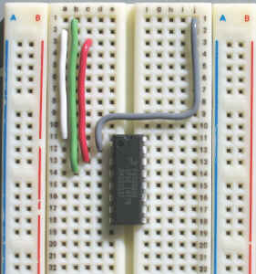
In the Physics 4D06 lab, an ISP ribbon cable is provided so that you can do your MCU development on a breadboard. In order to use this feature, remove the MC9S08QG8 from the DEMO9S08QG8 board and install one on your breadboard. Wire the four ISP lines as shown in the photograph.
| 1 | GND | MCU PIN-4 | GREEN | 16 | BKGD | MCU PIN-2 GREY |
| 2 | RESET | MCU PIN-1 | WHITE | 15 | ||
| 3 | VDD | MCU PIN-3 | RED | 14 | ||
| 4 | 13 | |||||
| 5 | 12 | |||||
| 6 | 11 | |||||
| 7 | 10 | |||||
| 8 | 9 |
16-pin ISP connection to MC9S08QG8
Note that the pin numbers on the 16-pin plug are opposite to those on the 6-pin header.
The MCU is normally powered by +3.3V from the USB cable. Power from the breadboard's +5V supply is not required to program the MCU. If you choose to power the MCU from the breadboard's +5V supply, do not connect +5V to the ISP cable, that is, remove the RED wire shown in the photograph.
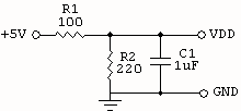
Note that the supply voltage VDD must not exceed 3.6V. Use a 3.3V or 3.6V voltage regulator, or use a simple voltage divider using one 100-ohm and one 220-ohm resistor to drop the voltage down from the 5V supply as shown below.
The purpose of this program is to flash an LED once every second, i.e 0.5sec on followed by 0.5sec off. This program uses a software delay loop.
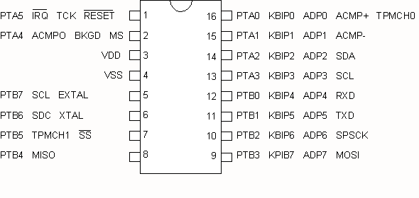
Install an LED with a 220-series resistor at any of the 6 pins, pin 7, 8, 9,
10, 11, 12. and observe the flashing.
| #include <MC9S08QG8.h> | |||
| void Delay(unsigned long delay); | |||
| void main() | |||
| { | |||
| SOPT1 = 0x52; | // disable COP watchdog | ||
| PTBDD = 0b00111111; | // set PTB0-5 as output | ||
| // select XTAL | |||
| ICSC1 = 0b10000000; | |||
| ICSC2 = 0b00110110; | |||
| for (;;) | // endless loop | ||
| { | |||
| PTBD = 0b00111111; | // set PTB0-5 high | ||
| Delay(6000); | |||
| PTBD = 0; | |||
| Delay(6000); | |||
| } | |||
| } | |||
| void Delay(unsigned long delay) | |||
| { | |||
| unsigned long i; | |||
| for (i=0; i<= delay;i++) | |||
| { | |||
| } | |||
| } | |||
Connect Vss to GND
2006.11.09 - 2012.03.14