|
|
|
Freescale
MC9S08QG8/4
|
|
|
Code
Example #7
|
| 2011.12.31 | ||
| 2012.01.01 | - recent update | |
| - added LCD info | ||
| - added Example 4. | ||
| 2012.01.13 | - Introduction to Examples | |
| - added explanations, various comments | ||
| - added example 5 | ||
| 2012.01.15 | - Global and local variables | |
| - Stacks | ||
| 2012.01.16 | - Interrupts | |
| 2012.01.19 | - 7-Segment LED interface | |
| 2012.02.13 | - Example #10 - Four 7-segment LED multiplexed | |
| 2012.02.14 | - Modifications to Example #10 | |
| 2012.03.14 | - Examples on individual pages | |
| Example #1 | Simple ASM program vs C program | |
| Watchdog Memory I/O Model Page Zero Addressing Infinite Loop External Crystal |
||
| Example #2 | Flashing LED |
|
| Software delay | ||
| Example #3 | Character Output | |
| Serial Transmit Data LCD Display Function Prototypes |
||
| Example #4 | Text Message | |
| Characters, Strings and Pointers |
||
| Example #5 | Timer test with oscilloscope |
|
| Example #6 | Timer test with flashing LED | |
| Gobal and Local variables Stacks Subroutines |
||
| Example #7 | Timer test with flashing LED using interrupts | |
| Interrupts | ||
| Example #8 | Single Hexadecimal Display on 7-segment LED | |
| Common Cathode Display | ||
| Example #9 | Single Hexadecimal Display on 7-segment LED | |
| Common Anode Display | ||
| Example #10 | Four multiplexed 7-segment Common Anode LED | |
| Displaying decimal digits Switch/Case statements |
||
| Example #11 | Four multiplexed 7-segment Common Anode LED | |
| Displaying 8-bit and 16-bit integers as hexadecimal digits | ||
The interrupt mechanism is very similar to a subroutine call and return with some important differences. For interrupts to function, the master Interrupt Mask must be set to zero using the CLI instruction (CLear Interrupt mask). Interrupts can occur at any time during program execution and does not require a specific BSR or JSR to be executed. The processor must complete an instruction in process before the interrupt process begins. The interrupt mask flag is set to prevent further interrupts. The current state of the registers, flags and PC are pushed on to the stack and the interrupt service subroutine is executed. On termination of the interrupt service routine, the RTI (ReTurn from Interrupt instruction is executed.) By executing the RTI instruction, the state of the machine is restored and the processor resumes instruction execution from where it left off.
The purpose of this example is to explore the usage timer interrupts to flash an LED. This program will turn on the LED for one second and off for one second.
Set up conditions: Remove the external 8MHz crystal and 22M-ohm resistor. Connect the LED in series with a 330-ohm resistor between a PortB output pin and GND.
#include <MC9S08QG8.h>


// Declare global constants here

#define COUNT_LIMIT 61


// Declare global variables

byte TimerCount;


void EnableInterrupts(void)

{asm

{
CLI


}

}


void Init(void)

{

 SOPT1 = 0x52; // disable COP watchdog

PTBDD = 0b11111111; // set PTB0-7 as output


// initialize MTIM (8-bit timer module)

// XTAL = 8MHz

// BUSCLK = 4MHz

// divide by 256, period = 64us

MTIMCLK = 0b00001000;

MTIMSC = 0; // Start the timer


}


// example of ISR for Modulo Timer Overflow

void interrupt 12 TimerISR(void)

{

byte status;

// toggle PortB bits

// read Timer Status

status = MTIMSC;

// restart Timer

MTIMSC = 0b01000000;

if (TimerCount++ >= COUNT_LIMIT)

{
 TimerCount = 0;

// toggle output

PTBD = ~PTBD;


}

}


void main(void)

{
 Init(); // Initialize hardware


// Endless loop, nothing to do here

for(;;)

{
}
}
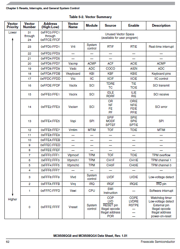
Every hardware feature or module that is capable of interrupting the CPU is given an Interrupt Vector Number (IVN) by the manufacturer of the MCU (Freescale Semiconductor). This number determines where in the Interrupt Vector Table the address of the Interrupt Service Routine (ISR) is located. The MTIM module is assigned IVN 12. In the twelfth position of the table the address of TimerISR is stored by the IDE programmer. Note that the name of the ISR (TimerISR) is arbitrary. You can choose any name.
The IVN for all hardware modules are found in the MC9S08QG8 Data Sheet (300 pages 3MB pdf).
The page is shown here:
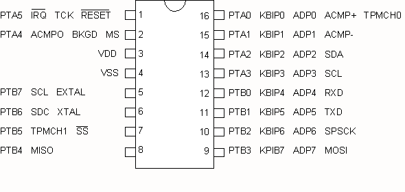
Connect Vss to GND
2006.11.09 - 2012.03.14