|
|
|
Freescale
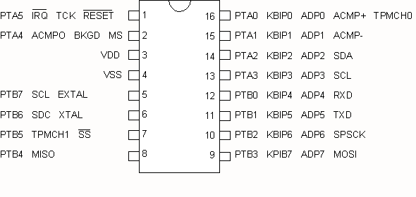
MC9S08QG8/4
|
|
|
Code
Example #6
|
| 2011.12.31 | ||
| 2012.01.01 | - recent update | |
| - added LCD info | ||
| - added Example 4. | ||
| 2012.01.13 | - Introduction to Examples | |
| - added explanations, various comments | ||
| - added example 5 | ||
| 2012.01.15 | - Global and local variables | |
| - Stacks | ||
| 2012.01.16 | - Interrupts | |
| 2012.01.19 | - 7-Segment LED interface | |
| 2012.02.13 | - Example #10 - Four 7-segment LED multiplexed | |
| 2012.02.14 | - Modifications to Example #10 | |
| 2012.03.14 | - Examples on individual pages | |
| Example #1 | Simple ASM program vs C program | |
| Watchdog Memory I/O Model Page Zero Addressing Infinite Loop External Crystal |
||
| Example #2 | Flashing LED |
|
| Software delay | ||
| Example #3 | Character Output | |
| Serial Transmit Data LCD Display Function Prototypes |
||
| Example #4 | Text Message | |
| Characters, Strings and Pointers |
||
| Example #5 | Timer test with oscilloscope |
|
| Example #6 | Timer test with flashing LED | |
| Gobal and Local variables Stacks Subroutines |
||
| Example #7 | Timer test with flashing LED using interrupts | |
| Interrupts | ||
| Example #8 | Single Hexadecimal Display on 7-segment LED | |
| Common Cathode Display | ||
| Example #9 | Single Hexadecimal Display on 7-segment LED | |
| Common Anode Display | ||
| Example #10 | Four multiplexed 7-segment Common Anode LED | |
| Displaying decimal digits Switch/Case statements |
||
| Example #11 | Four multiplexed 7-segment Common Anode LED | |
| Displaying 8-bit and 16-bit integers as hexadecimal digits | ||
The purpose of this example is to explore the usage of the simple 8-bit Timer Module MTIM using an LED. This program will turn on the LED for one second and off for one second.
Set up conditions: Remove the external 8MHz crystal and 22M-ohm resistor.
Connect the LED in series with a 330-ohm resistor between a PortB output pin
and GND.
#include <MC9S08QG8.h>


// Declare global constants here

#define COUNT_LIMIT 61


// Declare global variables

byte TimerCount;


void Init(void)

{

 SOPT1 = 0x52; // disable COP watchdog

PTBDD = 0b11111111; // set PTB0-7 as output


// initialize MTIM (8-bit timer module)

// XTAL = 8MHz

// BUSCLK = 4MHz

// divide by 256, period = 64us

MTIMCLK = 0b00001000;

MTIMSC = 0; // Start the timer


}


void main(void)

{
 Init(); // Initialize hardware


// Endless loop

for(;;)

{
while (MTIMSC_TOF == 0);


// clear TOF by writing to MTIMSC

MTIMSC = 0;


if (TimerCount++ >= COUNT_LIMIT)

{
 TimerCount = 0;

// toggle PortB bits

PTBD = ~PTBD;
}

}
}
TOF is a specific bit (bit-7) of the hardware register called MTIMSC (Timer Status and Control register. Since the actual physical address of registers and bit assignments may change from one MCU model to another, it is best to use the manufacturers default symbol names. The function of hardware registers and assigned bits can be found in the MCU Data Manual. The names of the registers and specific bits can be found in the header file named MC9S08QG8.h.
The following statement,
while (MTIMSC_TOF == 0);
tests for the condition that the Timer Overflow bit (TOF) is zero, i.e., the 8-bit timer value MTIMCNT has not exceeded 255. This statement is continuously executed as long as TOF is zero. When TOF becomes one, execution proceeds to the next statement. It is advisable to disassemble the C code and examine the ASM code that the compiler produces.
The expression,
~PTBD
takes the 1's complement of the PortB, i.e. all eight bits of PortB are inverted.
PTBD = ~PTBD;
The complete statement sends the complement of PortB back to PortB, hence toggles all eight bits of PortB every time this statement is executed.
A global varible is data that remains at a fixed location in memory and can be accessed by any program or subroutine. Global variables are declared at the top of the program and must appear outside of all main() body or subprogram definitions.
A local varible is data that is used within the main program or subprogram only and its "scope" is restricted to that program or subprogram only. A local variable cannot be accessed by any instruction ouside of the subprogram in which it is declared. The data is transient and will vanish when the propram or subprogram is exited. The data stored in a local variable is not retained on subsequent entries to the same subprogram.
Local variables are declared within the body of the main() program or subprogram.
// Declare global constants here

#define COUNT_LIMIT 61


// Declare global variables here

byte Count;


void main(void)

{
// declare local variables here

byte count;


for(count = 0; count< COUNT_LIMIT; count++)

{

}
}
Global variables are permanent and fixed memory locations. Local varibles are transient, relocatable and created using a stack.
A stack is an area in memory (called a buffer) for storing information private to a subroutine. Stacks are an efficient and useful technique for organizing information passed from one subroutine to another. Stacks are implemented using what is known as a first-in last-out buffer or FILO.
Imagine a stack of plates or serving trays in a cafeteria. The first plate goes to the bottom of the stack and becomes the last to be retrieved. Conversely, the last plate placed on the stack is the first to be take off.
Not all microcontrollers provide a stack feature and instructions. MCUs that do implement stacks in hardware will provide instructions to manipulate the stack. This includes an address register called the STACK POINTER (SP) and instructions, PUSH or PSH, to push data on to the stack. The opposite instruction to retrieve data from the stack is PULL or POP.
A stacks is also an effective way to save a return address and data when a subroutine or an interrupt handler routine is invoked.
Programs can very rapidly grow into an unmanageable mess of tangled code which we call "spaghetti code". In order to prevent this from happening it is important to divide a complex task in smaller manageable modules. We do this with the creation of subroutines or subprograms. You have already seen how subroutines are created and called in a C program.
//Subroutine

void Init(void)

{

}


void main(void)

{
// call the subroutine

Init();


}
Disassemble your C program and examine the instructions that are used to call a subroutine.
In assembler, the BSR and JSR (Branch to Subroutine and Jump to Subroutine) operations will cause the processor to start execuing the instructions in the subroutine. To return to the program that initiated the call the RTS (ReTurn from Subroutine) instruction is used.
| void Init() | |||||
| { | |||||
| asm | |||||
| { | |||||
| RTS | // return to calling program | ||||
| } | |||||
| } | |||||
| void main() | |||||
| { | |||||
| asm | |||||
| { | |||||
| BSR Init | // branch to subroutine | ||||
| } | |||||
| } | |||||
How does the processor know which address to which to return? When the BSR or JSR instruction is executed, the address (the Program Counter or PC) of the next instruction is pushed on to the stack. The next sequence is equivalent to a BRA or JMP instruction where instruction execution continues at the address of the subroutine. At the end of the subroutine the RTS instruction is executed which pops the address off the stack and sets it into the Program Counter.
Connect Vss to GND
2006.11.09 - 2012.03.14