|
|
|
Freescale
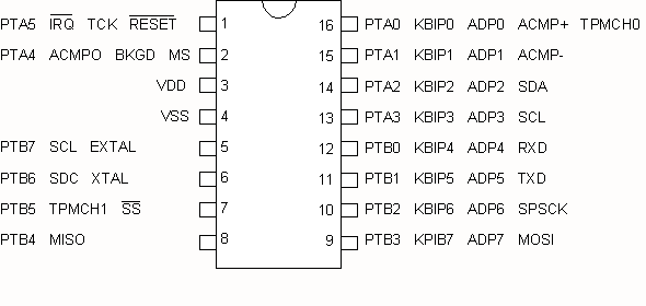
MC9S08QG8/4
|
|
|
Code
Example #5
|
| 2011.12.31 | ||
| 2012.01.01 | - recent update | |
| - added LCD info | ||
| - added Example 4. | ||
| 2012.01.13 | - Introduction to Examples | |
| - added explanations, various comments | ||
| - added example 5 | ||
| 2012.01.15 | - Global and local variables | |
| - Stacks | ||
| 2012.01.16 | - Interrupts | |
| 2012.01.19 | - 7-Segment LED interface | |
| 2012.02.13 | - Example #10 - Four 7-segment LED multiplexed | |
| 2012.02.14 | - Modifications to Example #10 | |
| 2012.03.14 | - Examples on individual pages | |
| Example #1 | Simple ASM program vs C program | |
| Watchdog Memory I/O Model Page Zero Addressing Infinite Loop External Crystal |
||
| Example #2 | Flashing LED |
|
| Software delay | ||
| Example #3 | Character Output | |
| Serial Transmit Data LCD Display Function Prototypes |
||
| Example #4 | Text Message | |
| Characters, Strings and Pointers |
||
| Example #5 | Timer test with oscilloscope |
|
| Example #6 | Timer test with flashing LED | |
| Gobal and Local variables Stacks Subroutines |
||
| Example #7 | Timer test with flashing LED using interrupts | |
| Interrupts | ||
| Example #8 | Single Hexadecimal Display on 7-segment LED | |
| Common Cathode Display | ||
| Example #9 | Single Hexadecimal Display on 7-segment LED | |
| Common Anode Display | ||
| Example #10 | Four multiplexed 7-segment Common Anode LED | |
| Displaying decimal digits Switch/Case statements |
||
| Example #11 | Four multiplexed 7-segment Common Anode LED | |
| Displaying 8-bit and 16-bit integers as hexadecimal digits | ||
The purpose of this example is to explore the usage of the simple 8-bit Timer Module MTIM.
Students of Physics 4D06 would normally have access to an oscilloscope which would aid in program testing. This exercise is also written for cases when an oscilloscope is not available and a single LED is used to confirm proper program operation.
Set up conditions: Remove the external 8MHz crystal and 22M-ohm resistor.
#include <MC9S08QG8.h>


void Init(void)

{

SOPT1 = 0x52; // disable COP watchdog

PTBDD = 0b11111111; // set PTB0-7 as output


// initialize MTIM (8-bit timer module)

// XTAL = 8MHz

// BUSCLK = 4MHz

// divide by 256, period = 64us

MTIMCLK = 0b00001000;

MTIMSC = 0; // Start the timer


}


void main(void)

{
 Init(); // Initialize hardware


// Endless loop

for(;;)

{

// Read the timer count and send to PortB

PTBD = MTIMCNT;

}
}
This exercise requires the use of an oscilloscope. Measure and draw the waveforms of the outputs of each of the eight pins of PortB, beginning with PTB7 and progressing to PTB0. Pay particular attention to the measured period of each waveform. Relate your measurements with the frequency of the internal CLOCK frequency. You will notice a dramatic change when measuring PTB1 and PTB0. Can you explain this behaviour?
Connect Vss to GND
2006.11.09 - 2012.03.14