|
|
|
Freescale
MC9S08QG8/4
|
|
|
Getting
Started
|
|
Please note that the DEMO9S08QG8 or APS08QG8SLK requires
a PC with a USB connection.
|
If you have purchased the DEMO9S08QG8 or APS08QG8SLK developmental kit, follow the Quick Start Guide that comes with the kit in order to install CodeWarrior IDE.
Basically, here are the things you need do:
Metrowerks CodeWarrior and the Service Pack can be downloaded from www.metrowerks.com
You do not need to purchase the developmental kit in order to run the simulator only.
A new license key from Metrowerks is not required if your code is less than 1K bytes long.
(Note: Metrowerks is now part of Freescale Semiconductor).
If you are planning on using the MC9S08QG8/4 chip in an actual hardware project, you should plan on installing an ISP (In-System Programming) connector on your project board. By doing so you can program your MCU without having to remove the chip. Prepare your project circuit board with an 8-pin or 16-pin DIP socket for your MCU as required. Remove the MCU from the DEMO9S08QG8 board. Install a 6-pin header on the board where it is marked BDM PORT.
Install a similar 6-pin header on your project board. Wire this 6-pin header as shown in the table below. Obtain a 6-pin ribbon cable with female connectors to mate with the 6-pin headers and connect the two boards together.
| 1 | BKGD | MCU PIN-2 | 2 | GND | MCU PIN-4 | |
| 3 | 4 | RESET | MCU PIN-1 | |||
| 5 | 6 | VDD | MCU PIN-3 |
Install your target MC9S08QG8/4 MCU chip onto your project's circuit board.
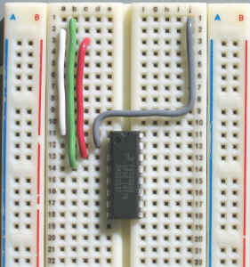
In the Physics 4D06 lab, an ISP ribbon cable is provided so that you can do your MCU development on a breadboard. In order to use this feature, remove the MC9S08QG8 from the DEMO9S08QG8 board and install one on your breadboard. Wire the four ISP lines as shown in the photograph.
| 1 | GND | MCU PIN-4 | GREEN | 16 | BKGD | MCU PIN-2 GREY |
| 2 | RESET | MCU PIN-1 | WHITE | 15 | ||
| 3 | VDD | MCU PIN-3 | RED | 14 | ||
| 4 | 13 | |||||
| 5 | 12 | |||||
| 6 | 11 | |||||
| 7 | 10 | |||||
| 8 | 9 |
16-pin ISP connection to MC9S08QG8
Note that the pin numbers on the 16-pin plug are opposite to those on the 6-pin header.
The MCU is normally powered by +3.3V from the USB cable. Power from the breadboard's +5V supply is not required to program the MCU. If you choose to power the MCU from the breadboard's +5V supply, do not connect +5V to the ISP cable, that is, remove the RED wire shown in the photograph.
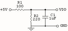
Note that the supply voltage VDD must not exceed 3.6V. Use a 3.3V or 3.6V voltage regulator, or use a simple voltage divider using one 100-ohm and one 220-ohm resistor to drop the voltage down from the 5V supply as shown below.
To start a new project, follow the instructions found in the Quick Start guide. This is summarized as follows:
Follow the New Project Wizard pages:
You can setup your Editor Preferences to set the way the editor formats your code. Select Edit, Preferences..., Editor, Code Formatting and enable all the selection boxes.
From the project window, click on the + sign beside Sources and double click on main.c
Your program is a text file and will appear in a window titled main.c.
For now, delete everything in main.c and start with a clean window.
We begin with the basic structure of a C program as shown:
| void main() | |||
| { | |||
| } | |||
Type this in. The first line is the header of the procedure called main(). The body of the procedure will be the lines contained between the two curly brackets. You may add your own comments as follows:
|
// a single line comment looks like this /* blocks of comments or commented out code can be enclosed like this */ |
At this point you have three options. You can select Project, Compile and the compiler will check for warnings or errors. You can also select Disassemble to show a listing of the assembled code. You may also select Debug to execute the code.
If your target selection is P&E FCS (Full Chip Simulation) then you can simulate the program without requiring the DEMO board to be connected.
In order to download the assembled code to your target MCU you must select P&E ICD.
It would be so easy to develop all of your code in C. However, since the purpose of this course is to teach microcomputer fundamentals it is very valuable to be able to understand and write your own code in assembly language. Take the time to disassemble your C program and learn how the C code is compiled into assembler code.
Disassemble this procedure and you will find that it ends with the single instruction RTS (Return from Subroutine). Thus the main() procedure will return to the calling program after it has been executed.
| #include <MC9S08QG8.h> | |||||
| void main() | |||||
| { | |||||
| asm | |||||
| { | |||||
| LDA #$52 | |||||
| STA SOPT1 | ; disable COP watchdog | ||||
| MOV #$08,PTBDD | ; set PTB3 as output | ||||
| loop: | |||||
| MOV #$08,PTBD | ; pulse PTB3 high | ||||
| MOV #$00,PTBD | |||||
| BRA loop | ; endless loop | ||||
| } | |||||
| } | |||||
The first line tells the compiler to use the predefined MCU register definitions found in the file MC9S08QG8.h. The <> brackets are used to specify that the file is located in the system folder. Use " " instead if you wish to use files kept in your local folder. Look at the project window, find and open MC9S08QG8.h to see how these registers are defined.
| Register Name | Register Description |
| PTAD | Port A Data register |
| PTADD | Port A Data Direction register ( 0 = input, 1 = output ) |
| PTBD | Port B Data register |
| PTBDD | Port B Data Direction register ( 0 = input, 1 = output ) |
The asm{ } block defines a block of assembler code, using standard assembly programming language syntax.
Create the same program in C.
| #include <MC9S08QG8.h> | |||
| void main() | |||
| { | |||
| SOPT1 = 0x52; | // disable COP watchdog | ||
| PTBDD = 0x08; | // set PTB3 as output | ||
| for (;;) | // endlessloop | ||
| { | |||
| PTBD = 0x08; | // pulse PTB3 high | ||
| PTBD = 0x00; | |||
| } | |||
| } | |||
The for (;;) { } creates a C equivalent of an endless loop.
Disassemble this C program and compare the code with the previous ASM program.
Run both of these programs. Draw the waveforms at the output pin (PTB3 = pin 9) and measure the execution times of the statements responsible for generating this waveform. Compare your results with the cycle times given in the instruction tables.
Another way for creating an endless loop in C is using the while() statement. This C compiler will flag this with a warning even thought this is syntatically and programmatically correct.
| #include <MC9S08QG8.h> | |||
| void main() | |||
| { | |||
| SOPT1 = 0x52; | // disable COP watchdog | ||
| PTBDD = 0x08; | // set PTB3 as output | ||
| for (1) | // endlessloop | ||
| { | |||
| PTBD = 0x08; | // pulse PTB3 high | ||
| PTBD = 0x00; | |||
| } | |||
| } | |||
Connect Vss to GND
2006.11.09 - 2011.12.21