|
|
|
Freescale
MC9S08QG8/4
|
|
|
Code
Example #1
|
| 2011.12.31 | ||
| 2012.01.01 | - recent update | |
| - added LCD info | ||
| - added Example 4. | ||
| 2012.01.13 | - Introduction to Examples | |
| - added explanations, various comments | ||
| - added example 5 | ||
| 2012.01.15 | - Global and local variables | |
| - Stacks | ||
| 2012.01.16 | - Interrupts | |
| 2012.01.19 | - 7-Segment LED interface | |
| 2012.02.13 | - Example #10 - Four 7-segment LED multiplexed | |
| 2012.02.14 | - Modifications to Example #10 | |
| 2012.03.14 | - Examples on individual pages | |
| Example #1 | Simple ASM program vs C program | |
| Watchdog Memory I/O Model Page Zero Addressing Infinite Loop External Crystal |
||
| Example #2 | Flashing LED |
|
| Software delay | ||
| Example #3 | Character Output | |
| Serial Transmit Data LCD Display Function Prototypes |
||
| Example #4 | Text Message | |
| Characters, Strings and Pointers |
||
| Example #5 | Timer test with oscilloscope |
|
| Example #6 | Timer test with flashing LED | |
| Gobal and Local variables Stacks Subroutines |
||
| Example #7 | Timer test with flashing LED using interrupts | |
| Interrupts | ||
| Example #8 | Single Hexadecimal Display on 7-segment LED | |
| Common Cathode Display | ||
| Example #9 | Single Hexadecimal Display on 7-segment LED | |
| Common Anode Display | ||
| Example #10 | Four multiplexed 7-segment Common Anode LED | |
| Displaying decimal digits Switch/Case statements |
||
| Example #11 | Four multiplexed 7-segment Common Anode LED | |
| Displaying 8-bit and 16-bit integers as hexadecimal digits | ||
If you are planning on using the MC9S08QG8/4 chip in an actual hardware project, you should plan on installing an ISP (In-System Programming) connector on your project board. By doing so you can program your MCU without having to remove the chip. Prepare your project circuit board with an 8-pin or 16-pin DIP socket for your MCU as required. Remove the MCU from the DEMO9S08QG8 board. Install a 6-pin header on the board where it is marked BDM PORT.
Install a similar 6-pin header on your project board. Wire this 6-pin header as shown in the table below. Obtain a 6-pin ribbon cable with female connectors to mate with the 6-pin headers and connect the two boards together.
| 1 | BKGD | MCU PIN-2 | 2 | GND | MCU PIN-4 | |
| 3 | 4 | RESET | MCU PIN-1 | |||
| 5 | 6 | VDD | MCU PIN-3 |
Install your target MC9S08QG8/4 MCU chip onto your project's circuit board.
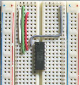
In the Physics 4D06 lab, an ISP ribbon cable is provided so that you can do your MCU development on a breadboard. In order to use this feature, remove the MC9S08QG8 from the DEMO9S08QG8 board and install one on your breadboard. Wire the four ISP lines as shown in the photograph.
| 1 | GND | MCU PIN-4 | GREEN | 16 | BKGD | MCU PIN-2 GREY |
| 2 | RESET | MCU PIN-1 | WHITE | 15 | ||
| 3 | VDD | MCU PIN-3 | RED | 14 | ||
| 4 | 13 | |||||
| 5 | 12 | |||||
| 6 | 11 | |||||
| 7 | 10 | |||||
| 8 | 9 |
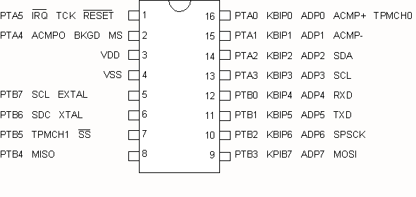
16-pin ISP connection to MC9S08QG8
Note that the pin numbers on the 16-pin plug are opposite to those on the 6-pin header.
The MCU is normally powered by +3.3V from the USB cable. Power from the breadboard's +5V supply is not required to program the MCU. If you choose to power the MCU from the breadboard's +5V supply, do not connect +5V to the ISP cable, that is, remove the RED wire shown in the photograph.
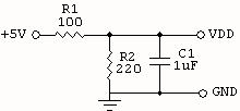
Note that the supply voltage VDD must not exceed 3.6V. Use a 3.3V or 3.6V voltage regulator, or use a simple voltage divider using one 100-ohm and one 220-ohm resistor to drop the voltage down from the 5V supply as shown below.
| #include <MC9S08QG8.h> | |||||
| void main() | |||||
| { | |||||
| asm | |||||
| { | |||||
| LDA #$52 | |||||
| STA SOPT1 | ;disable COP watchdog | ||||
| MOV #$08,PTBDD | ;set PTB3 as output | ||||
| loop: | |||||
| MOV #$08,PTBD | ;pulse PTB3 high | ||||
| MOV #$00,PTBD | |||||
| BRA loop | ; endless loop | ||||
| } | |||||
| } | |||||
The first line tells the compiler to use the predefined MCU register definitions found in the file MC9S08QG8.h. The <> brackets are used to specify that the file is located in the system folder. Use " " instead if you wish to use files kept in your local folder. Look at the project window, find and open MC9S08QG8.h to see how these registers are defined.
| Register Name | Register Description |
| PTAD | Port A Data register |
| PTADD | Port A Data Direction register ( 0 = input, 1 = output ) |
| PTBD | Port B Data register |
| PTBDD | Port B Data Direction register ( 0 = input, 1 = output ) |
The asm{ } block defines a block of assembler code, using standard assembly programming language syntax.
Create the same program in C.
| #include <MC9S08QG8.h> | |||
| void main() | |||
| { | |||
| SOPT1 = 0x52; | // disable COP watchdog | ||
| PTBDD = 0x08; | // set PTB3 as output | ||
| for (;;) | // endless loop | ||
| { | |||
| PTBD = 0x08; | // pulse PTB3 high | ||
| PTBD = 0x00; | |||
| } | |||
| } | |||
The for (;;) { } creates a C equivalent of an endless loop.
Disassemble this C program and compare the code with the previous ASM program.
Run both of these programs. Draw the waveforms at the output pin (PTB3 = pin 9) and measure the execution times of the statements responsible for generating this waveform. Compare your results with the cycle times given in the instruction tables.
The ASM program shown about requires 11 clock cycles to execute. With an external 8MHz crystal (more about this is yet to come) the system CLK is 4MHz. Thus the execution time = 11 x 0.25us = 2.75us. This example uses the internal RC oscillator. Hence the CLK may not be exactly 4MHz.
Hexadecimal values are preceded by 0x or $. For example, 0xF3
or $F3.
Binary values are preceded by 0b. For example, 0b11110011.
All literal constants must be preceded by #. For example, #$15, #0x15, #21, #0b00010101 are all the same value.
Note that C is case sensitive. Assembler opcodes (operational instruction codes) are not case sensitve.
C statements are generally terminated with a semi-colon ; - This will be clarified later.
The COP (Computer Operating Properly) watchdog is a fault detection mechanism in case the MCU program runs into trouble and fails to run in its preconceived loop. If a hardware monostable multivibrator times out, a fault is assumed and the MCU performs a system reset. To prevent a timeout, the program must periodically trigger the monostable (less than 256 ms is default setting) using the _RESET_WATCHDOG( ) function or by writing to the SRS register. Note that the COP watchdog is enabled in default setting on startup
The Motorola/Freescale memory/peripheral addressing model treats all peripheral hardware registers the same as memory locations. This makes possible some very convenient and efficient operations. Any instruction that can be performed on a memory location can also be performed on a hardware register. Furthermore, Motorola/Freescale puts the most commonly used hardware registers on Page Zero.
Page-0 refers to all 256 memory locations from $0000 to $00FF. What is special about this is that the upper byte (8 bits) of the 16-bit address is zero. With this assumption, it only requires a single byte to reference an address on Page-0. Hence Page-0 memory reference instructions are one byte shorter and takes one less execution cycle. In the example below, PTBD is a Page-0 address. Hence the MOV instruction can apply here.
| MOV #0x08, PTBD |
In the following example, the SOPT1 hardware register is not frequently used and has been allocated a memory location above Page-0, i.e. it requires an Extended Address, 16-bits long. In this case the MOV instruction cannot be used. Two instructions are required to set this register.
| LDA #$52 | |||||
| STA SOPT1 |
Another way for creating an endless loop in C is using the while() statement. This C compiler will flag this with a warning even thought this is syntatically and programmatically correct.
| #include <MC9S08QG8.h> | |||
| void main() | |||
| { | |||
| SOPT1 = 0x52; | // disable COP watchdog | ||
| PTBDD = 0x08; | // set PTB3 as output | ||
| while (1) | // endless loop | ||
| { | |||
| PTBD = 0x08; | // pulse PTB3 high then low | ||
| PTBD = 0x00; | |||
| } | |||
| } | |||
Connect Vss to GND
2006.11.09 - 2012.03.14